- 您现在的位置:买卖IC网 > Sheet目录471 > MAX19997AETX+T (Maxim Integrated)IC DOWNCONVERTER 2CH 36TQFN
MAX19997A
Dual, SiGe High-Linearity, 1800MHz to 2900MHz
Downconversion Mixer with LO Buffer
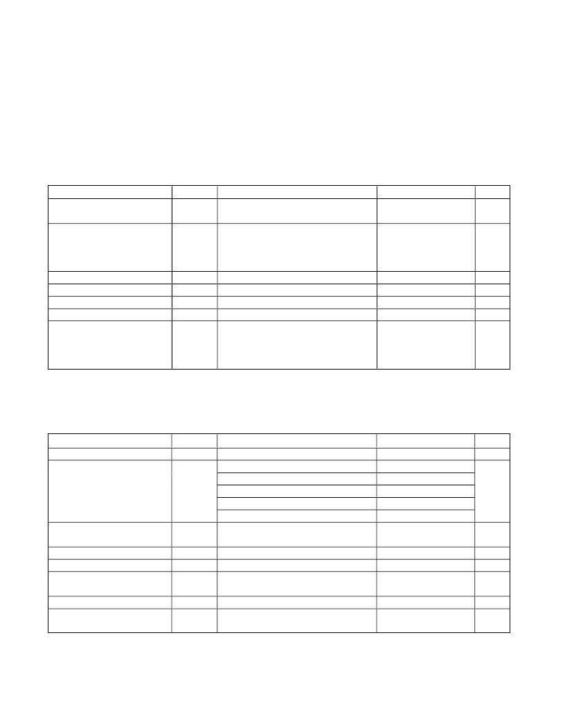
+5.0V SUPPLY, LOW-SIDE LO INJECTION AC ELECTRICAL CHARACTERISTICS
(continued)
(Typical Application Circuit optimized for the standard RF band (see Table 1) , V CC = 4.75V to 5.25V, RF and LO ports are driven
from 50 ? sources, P LO = -3dBm to +3dBm, P RF = -5dBm, f RF = 2300MHz to 2900MHz, f LO = 1950MHz to 2550MHz, f IF = 350MHz,
f RF > f LO , T C = -40°C to +85°C. Typical values are at V CC = 5.0V, P RF = -5dBm, P LO = 0dBm, f RF = 2600MHz, f LO = 2250MHz,
f IF = 350MHz, T C = +25°C, unless otherwise noted.) (Note 7)
PARAMETER
IF Output Impedance
SYMBOL
Z IF
CONDITIONS
Nominal differential impedance at the IC’s
IF outputs
MIN
TYP
200
MAX
UNITS
?
IF Output Return Loss
RF terminated into 50 ? , LO driven by 50 ?
source, IF transformed to 50 ? using
external components shown in the Typical
20
dB
Application Circuit
RF-to-IF Isolation
23.5
dB
LO Leakage at RF Port
2LO Leakage at RF Port
LO Leakage at IF Port
(Notes 8, 9)
-31
-27
-9.6
-24
dBm
dBm
dBm
RFMAIN (RFDIV) converted power
Channel Isolation
measured at IFDIV (IFMAIN) relative to
IFMAIN (IFDIV), all unused ports terminated
38.5
42
dB
to 50 ? (Notes 8, 9)
+3.3V SUPPLY, LOW-SIDE LO INJECTION AC ELECTRICAL CHARACTERISTICS
(Typical Application Circuit optimized for the standard RF band (see Table 1) . Typical values are at V CC = 3.3V, P RF = -5dBm,
P LO = 0dBm, f RF = 2600MHz, f LO = 2250MHz, f IF = 350MHz, T C = +25°C, unless otherwise noted.) (Note 7)
PARAMETER
Conversion Gain
SYMBOL
G C
(Note 9)
CONDITIONS
MIN
TYP
8.5
MAX
UNITS
dB
f RF = 2305MHz to 2360MHz
f RF = 2500MHz to 2570MHz
0.2
0.15
Conversion Gain Flatness
f RF = 2570MHz to 2620MHz
f RF = 2500MHz to 2690MHz
f RF = 2700MHz to 2900MHz
0.15
0.25
0.15
dB
Gain Variation Over Temperature
Input Compression Point
Third-Order Input Intercept Point
Third-Order Input Intercept
Variation Over Temperature
Noise Figure
Noise Figure Temperature
Coefficient
TC CG
IP 1dB
IIP3
NF SSB
TC NF
f RF = 2300MHz to 2900MHz,
T C = -40°C to +85°C
f RF1 - f RF2 = 1MHz, P RF = -5dBm per tone
f RF1 - f RF2 = 1MHz, T C = -40°C to +85°C
Single sideband, no blockers present
Single sideband, no blockers present,
T C = -40°C to +85°C
-0.01
7.7
19.7
±0.5
9.7
0.018
dB/°C
dBm
dBm
dBm
dB
dB/°C
Maxim Integrated
7
发布紧急采购,3分钟左右您将得到回复。
相关PDF资料
MAX19998ETP+
IC MIXER DOWNCONVERSION 20TQFN
MAX19999ETX+T
IC DOWNCONVERTER 2CH 36TQFN
MAX2009ETI+T
IC RF PREDISTORT ADJ 28-TQFN
MAX2010ETI+T
IC RF PREDISTORT ADJ 28-TQFN
MAX2014ETA+T
IC DETECT/CNTRL LOG 8-TDFN
MAX2015EUA+T
IC DETECT/CNTRL LOG 8-UMAX
MAX2015EVKIT
EVAL KIT FOR MAX2015
MAX2016ETI+T
IC DETECT/CNTRL LOG 28-TQFN
相关代理商/技术参数
MAX19998AETP+
功能描述:上下转换器 High-Gain 2.3GHz to 4.5GHz Downconv RoHS:否 制造商:Texas Instruments 产品:Down Converters 射频:52 MHz to 78 MHz 中频:300 MHz LO频率: 功率增益: P1dB: 工作电源电压:1.8 V, 3.3 V 工作电源电流:120 mA 最大功率耗散:1 W 最大工作温度:+ 85 C 安装风格:SMD/SMT 封装 / 箱体:PQFP-128
MAX19998AETP+T
功能描述:上下转换器 High-Gain 2.3GHz to 4.5GHz Downconv RoHS:否 制造商:Texas Instruments 产品:Down Converters 射频:52 MHz to 78 MHz 中频:300 MHz LO频率: 功率增益: P1dB: 工作电源电压:1.8 V, 3.3 V 工作电源电流:120 mA 最大功率耗散:1 W 最大工作温度:+ 85 C 安装风格:SMD/SMT 封装 / 箱体:PQFP-128
MAX19998AEVKIT#
制造商:Maxim Integrated Products 功能描述:SIGE HIGH-LINEARITY 2300MHZ TO 4000MHZ DOWNCONVERSION MIXER - Boxed Product (Development Kits)
MAX19998ETP+
功能描述:上下转换器 High-Gain 2.3GHz to 4.5GHz Downconv RoHS:否 制造商:Texas Instruments 产品:Down Converters 射频:52 MHz to 78 MHz 中频:300 MHz LO频率: 功率增益: P1dB: 工作电源电压:1.8 V, 3.3 V 工作电源电流:120 mA 最大功率耗散:1 W 最大工作温度:+ 85 C 安装风格:SMD/SMT 封装 / 箱体:PQFP-128
MAX19998ETP+T
功能描述:上下转换器 High-Gain 2.3GHz to 4.5GHz Downconv RoHS:否 制造商:Texas Instruments 产品:Down Converters 射频:52 MHz to 78 MHz 中频:300 MHz LO频率: 功率增益: P1dB: 工作电源电压:1.8 V, 3.3 V 工作电源电流:120 mA 最大功率耗散:1 W 最大工作温度:+ 85 C 安装风格:SMD/SMT 封装 / 箱体:PQFP-128
MAX19998EVKIT#
制造商:Maxim Integrated Products 功能描述:SIGE HIGH-LINEARITY 2300MHZ TO 4000MHZ DOWNCONVERSION MIXER - Boxed Product (Development Kits)
MAX19999A
功能描述:上下转换器
RoHS:否 制造商:Texas Instruments 产品:Down Converters 射频:52 MHz to 78 MHz 中频:300 MHz LO频率: 功率增益: P1dB: 工作电源电压:1.8 V, 3.3 V 工作电源电流:120 mA 最大功率耗散:1 W 最大工作温度:+ 85 C 安装风格:SMD/SMT 封装 / 箱体:PQFP-128
MAX19999ETX+
功能描述:上下转换器 High-Gain 3GHz to 4GHz Downconv RoHS:否 制造商:Texas Instruments 产品:Down Converters 射频:52 MHz to 78 MHz 中频:300 MHz LO频率: 功率增益: P1dB: 工作电源电压:1.8 V, 3.3 V 工作电源电流:120 mA 最大功率耗散:1 W 最大工作温度:+ 85 C 安装风格:SMD/SMT 封装 / 箱体:PQFP-128
